×

Message

EU e-Privacy Directive

This website uses cookies to manage authentication, navigation, and other functions. By using our website, you agree that we can place these types of cookies on your device.

View e-Privacy Directive Documents

View GDPR Documents

You have declined cookies. This decision can be reversed.

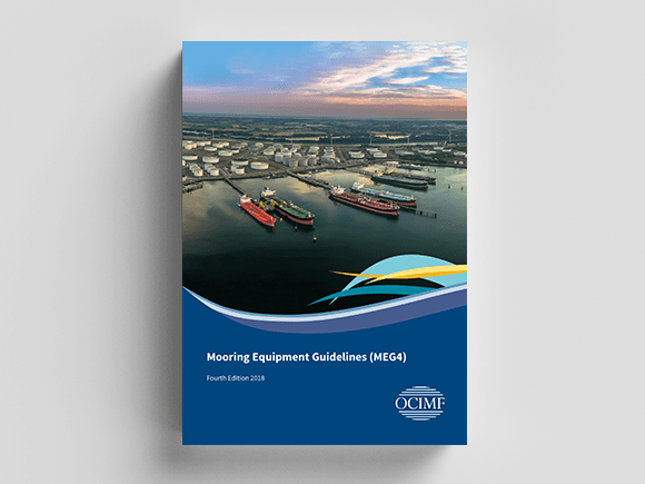
Mooring a ship to a berth is a common function for the maritime industry, however incidents that harm ship and terminal personnel still occur. 

This publication establishes recommended minimum requirements that will help ship designers, terminal designers, ship operators and mooring line manufacturers improve the design, performance and safety of mooring systems.

The updated MEG4 represents the output of a multi-discipline working group representing members of various shipping trade organisations, mooring line manufacturers, equipment suppliers, shipyards, and OCIMF members.

New chapters and key changes include:

  • Enhanced guidance for the purchasing, condition monitoring, and retirement of mooring lines and tails.
  • Enhanced guidance on documentation of mooring equipment.
  • New chapter on the Human Factors in Mooring Design.
  • New chapter on Jetty Design and Fittings.
  • New chapter on Ship Shore Interface.
  • New chapter on Alternative Technologies.

The guidance within MEG is sure to enhance the safety of mooring from the design of mooring arrangements using a Human Centred Design approach and an increased focus on the use and understanding of mooring lines and tails.

FAQs

Terminology can be confusing and common terms that are used across industry can mean different things to different groups. In the years since the Mooring Equipment Guidelines, Third Edition (MEG3) was published, there has been a misunderstanding of mooring lin720e strength terminology. One example is Minimum Breaking Load (MBL).

In MEG3, OCIMF defined MBL as "the minimum breaking load of a new dry mooring line or chain as declared by the manufacturer". But industry has also used MBL to mean test and calculation methods for mooring line break force. This has led to confusion between line users and manufacturers, and to differences between expected and actual mooring line performance. Eg. Similar mooring lines may in the past, have had a variation in tested break force of =/- 10%. Some Operators have purchased stronger ropes and adjusted winch brake setting to the increased rope MBL, thus reducing the safety factor between the line and winch.

Due to the use of the term Minimum Breaking Load, many mooring line users have come to the misunderstanding that lines can be safely loaded up to their MBL with no failures or degradation. This is not the case and OCIMF wants to make sure people understand the importance of safety margins on mooring lines. There is also confusion among some ship owners who incorrectly believe that mooring line certificates must exactly match the MBL requested.

To resolve this confusion, OCIMF has collaborated closely with the Cordage Institute, Eurocord, International Association of Classification Societies and Ship builders association to clearly define a set of terms and test methods for mooring line MBL that can be used consistently by both line users and manufacturers when designing, specifying, testing and operating mooring lines. These new terms will align the cordage and the tanker industries to a common language.

MEG3           MEG4

MBL              Ship Design MBL

                                                   Line Design Break Force (LDBF)

                                                   Working Load Limit (WLL)

 Figure 1.3 (page 8-9) and 1.4 (page 10) illustrates the relationship between strengths of mooring system components as per new terminology introduced in MEG4.

Introduction section of MEG4 states:

If new build ships under construction or existing ships are unable to follow the recommendation of this publication, they should, as a minimum, develop a Mooring System Management Plan (MSMP) and a Line Management Plan (LMP) that will:

-        Remain on the ship throughout its life as part of the management of change records

-        Identify a timeline and measures needed to follow the recommendations of this publication

-        Detail interim measures taken to address the recommendations in this publication, with reasons given for why the changes have not been implemented yet

Additionally, Section 3.3 and 3.4 provide guidance on factors to be considered for calculating Ship Design MBL with a simple process flow diagram in figure 3.2 (page 54). 

This could be undertaken for existing ships by determining ship design MBL as per figure 3.2 and then comparing against specified existing ship parameters. MSMP and LMP can then be developed to identify and implement mitigating measures, if there is a difference noted between the two comparisons. 

Figure 1.3 provides relative percentage values of mooring system components based on ship design MBL. With regards to strength relationships, recommended LDBC should be within 100-105% of Ship Design MBL. MEG4 aims to standardize a common reference point in the form of Ship Design MBL.


Not necessarily. OCIMF recognises that in some circumstances it may be unavoidable to exceed the WLL of the mooring line. The mooring line user will need to develop procedures for managing the risk posed by lines that have exceeded the WLL as part of their Mooring Safety Management Plan and Line Management Plan. This could be a combination of methods such as in service condition monitoring, testing samples of ropes that have been subjected to higher loads above WLL, wear zone assessment, detailed inspections and in cases where rope condition is above the rejection factor as per maker’s recommendations, retirement of the rope.

OCIMF provides guidance and recommendations of best practices. Introduction section of MEG4 states:

If new build ships under construction or existing ships are unable to follow the recommendation of this publication, they should, as a minimum, develop a Mooring System Management Plan (MSMP) and a Line Management Plan (LMP) that will:

-        Remain on the ship throughout its life as part of the management of change records.

-        Identify a timeline and measures needed to follow the recommendations of this publication.

-        Detail interim measures taken to address the recommendations in this publication, with reasons given for why the changes have not been implemented yet.

Additionally, Section 3.3 and 3.4 provide guidance on factors to be considered for calculating Ship Design MBL with a simple process flow diagram in figure 3.2 (page 54).


MSMP and LMP are both new tools to help operators manage equipment and lines from design, deployment through to retirement. 

Mooring System Management Plan (MSMP): Whilst updating MEG3, OCIMF became aware of inconsistencies in methods used for maintaining mooring equipment information. It is not unusual to find ship’s original design data, records for permanent equipment (e.g. winches and fittings), loose equipment (e.g. mooring lines, tails, stoppers) and risk assessments, all stored in separate locations. Consequently, information useful to ship’s personnel for their understanding on safe operation of mooring equipment in not always easy to locate. This becomes exacerbated if and when there is change of crew or vessel owner / operator.

MSMP has been created by OCIMF to help ship owners and operators keep consistent information about ship’s mooring equipment in one location.

Line Management Plan (LMP):  This is specific to individual mooring line and tail that contains ship operator’s requirements for management of mooring line / tail installation, maintenance, inspection and retirement criteria during the mooring lifecycle. Recommendations from mooring line/tail manufacturers need to be considered whilst developing the LMP.

It is recommended.  The ship operator is responsible for the development and implementation of the ship’s LMP. The LMP contains the ship operator’s requirements for the management of mooring line maintenance, inspection and retirement during the operational phase of the mooring line lifecycle.

The LMP can be a standalone tool or it may be integrated into existing safety or maintenance management systems. It can be available as hard or electronic copy, or both. Whatever the format, the LMP should be capable of being updated. It should be accessible for internal and external compliance verification, ship personnel training and communication with manufacturers. LMP information should be stored in a location that is easy for all users to access, e.g. on a computer system that can be accessed from both the ship and shore or compiled in a single physical location. It should be easy for the system users to access the LMP information from a single physical or virtual location.

The brake rendering should always be set to 60% of the ship design MBL. This is because the brake render setting point is the main protection for a ship’s mooring system and protects all parts of the mooring system by rendering at a specific pre-determined setting which is below all other failure loads but above line WLLs. The mooring winch brake becomes a weak link within the mooring system.

Mooring line MBL is no longer a recognized term in MEG4. However, OCIMF appreciates that it will take time for the terminology to be adopted throughout the industry. In such cases it depends on the reason that the terminal is asking for the line strength information. If this is not known, the Ship should either provide the terminal with both ship design MBL and LDBF values referencing alignment to MEG4, or request further clarification from the terminal. If the terminal needs the information for operational mooring analysis, then the LDBF values for each line should be provided.

It is important that brake rendering value is above the WLL of the line. When operational mooring analyses are carried out they verify that the Ship can remain safely moored for the given OCIMF Standard Environmental Criteria, within the given limits for heave surge and sway, without exceeding the maximum values for any of the mooring system components (shore hooks, lines, fittings and winches.) Thus, brake rendering values need to be higher than WLL values in order that the mooring studies can provide appropriate verification. If brakes rendered at WLL, software simulations would generate Ship movements that would exceed limits. i.e. It is important that there is a margin between brake rendering set point and the maximum loads to which lines should be exposed in maximum anticipated environmental conditions. Again, the mooring winch brake becomes a weak link within the mooring system.

Design Stage: At the design stage, a mooring analysis tool should be utilized to determine what restraint forces are required for the Ship. This output is the ship design MBL.

Operational Stage: Although technically more accurate to relate the WLL to the specific mooring LDBF, the differences between Ship Design MBL and LDBF of varying manufacturers will be negligible as LDBF should be within 100-105% of Ship Design MBL as per figure 1.3. Using Ship Design MBL allows for a single value for analysis and comparison. In any case, WLL values (limits) should be based on ship design MBL to meet standard OCIMF environmental criteria restraint requirements (defined in section 3).

Appendix A Introduction states that the wind coefficients for oil tankers are unchanged from the Mooring Equipment Guidelines, Third Edition.  These wind coefficients were reviewed with the conclusion that they remain valid for double-hulled tankers down to 16,000 DWT. 

For tankers less than 16,000 DWT consider using Classification Society Rules.

An Introduction to MEG4

Mooring Equipment Guidelines

Purchasing and Monitoring Mooring Lines and Tails

MEG4 Mooring System Design Principles

Addendums

The note (1) for ship size 266,00 is given as SP (spherical tanks). In this note, SP (spherical tanks) should be read as PR (prismatic tanks).
Rows 5–7 should have a white background.
The AL should be removed. Corrected formula:


The kN should be changed to kNm. Corrected formula:

The kN should be changed to kNm. Corrected formula:
Formula for Kex on should be read with a denominator of 3 instead of 10.
Drum diameter should be read as ≥ 16 x line diameter.